555 Timer Circuit Schematic - Adjustable Timer Circuit using 555 : If you want to learn more about the 555 timer, you should read, understand and do things on your own with 555 ic.
byAdmin•
0
555 Timer Circuit Schematic - Adjustable Timer Circuit using 555 : If you want to learn more about the 555 timer, you should read, understand and do things on your own with 555 ic.. Learn about the 555 timer and how it works in astable mode. The good thing is that this chip could work directly with 12v so no driver for the mosfet is needed. These styles of ics are very cheap and dependable in value whilst we in. Since the project only involves assembling a simple circuit by following the schematic, it will only take an hour to make. With this information you will learn how how the 555 works and will have the experience to build some of the circuits below.
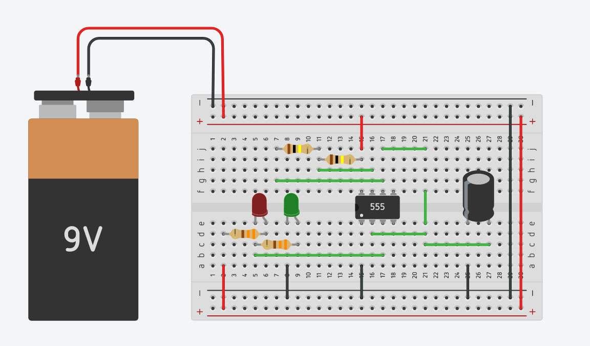
Print the diagram in the centre of a sheet of paper create a circuit using the ics pin locations. The 555 timer is a simple integrated circuit that can be used to make many different electronic circuits. The standard 555 timer ic is used in a variety of timer, pulse generation and oscillator applications. This tutorial provides sample circuits to set up a 555 timer in monostable, astable, and bistable modes as well as an in depth discussion of wiring info: The breadboard schematic of the above circuit is shown below.
555 Timer Remembering Astable and Monostable Circuits from www.petervis.com This means that the output voltage is a periodic pulse that alternates between the vcc value and 0 volts. The 555 timer shown above is configured as an astable circuit. The good thing is that this chip could work directly with 12v so no driver for the mosfet is needed. The book timer, op amp, and optoelectronic circuits and projects book vol. The circuit layout is for a 555 timer in astable mode. To observe the 555 timer in astable mode, let's build a circuit that uses the 555 timer's oscillating output to make. Generally, it's miles a monolithic timing circuit that offers unique and surprisingly stable delays of time or oscillation. Connect power and ground to pins 8 and 1 of the 555 timer (red and black wires).
To observe the 555 timer in astable mode, let's build a circuit that uses the 555 timer's oscillating output to make.
The good thing is that this chip could work directly with 12v so no driver for the mosfet is needed. The circuit layout is for a 555 timer in astable mode. Here is an efficient and economical circuit for a wireless remote camera flash trigger, useful for capturing scenes . I used a 9v supply. These fifteen 555 timer circuits are simple to make with widespread usability. The 555 timer, designed by hans camenzind in 1971. The 555 timer is a simple integrated circuit that can be used to make many different electronic circuits. You can watch the following video or read the written tutorial below. This 555 timer is in astable mode. The red section is the. The standard 555 timer ic is used in a variety of timer, pulse generation and oscillator applications. The 555 timer ic has found widespread use in a variety of applications, and is still used widely due so we will use the 10 kω resistor and two 10 μf capacitors in the timing circuit of the 555 timer. To observe the 555 timer in astable mode, let's build a circuit that uses the 555 timer's oscillating output to make.
A 555 timer is a very versatile. To observe the 555 timer in astable mode, let's build a circuit that uses the 555 timer's oscillating output to make. Look at the circuit diagram. This bistable configuration does not use any rc timing. The 555 timer shown above is configured as an astable circuit.
555 Timer - Frequency and Duty Cycle Calculator - Online ... from www.hobbyprojects.com The timer generates an output pulse with an on time period determined by the rc network i.e t = 1.1rc. For standard 555 timers use timing resistor values between 1k ohms and 1m ohms. With this information you will learn how how the 555 works and will have the experience to build some of the circuits below. The 555 timer shown above is configured as an astable circuit. The 555 timer, designed by hans camenzind in 1971. 7 below, you'll see the circuit schematic of the 555 and the parts relevant to it. You can use the 555 chips for basic timing functions, such as turning a light on for a certain when used in a schematic diagram, the pins of a 555 timer chip are almost always shown in the arrangement depicted here. The breadboard schematic of the above circuit is shown below.
For standard 555 timers use timing resistor values between 1k ohms and 1m ohms.
A 555 timer is a very versatile. And now a full schematic of the 555 timer oscillator with single step and free run option. This is the schematic below for the 555 timer that creates one square wave output. It's a simple source of oscillating in the schematic above, notice that the threshold pin and the trigger pin are connected to c1. The breadboard schematic of the above circuit is shown below. This 555 timer is in astable mode. Finally, power up your circuit by connecting the battery to your breadboard The 555 timer ic is an integrated circuit (chip) used in a variety of timer, delay, pulse generation, and oscillator applications. Look at the circuit diagram. Derivatives provide two (556) or four (558) timing circuits in one package. In this circuit, we will build a clock of about 60hz. Astable mode can produce digital square waveforms that go back and forth between. Lm555 timer internal circuit block diagram.
The schematic is shown in fig 5. A 555 timer is a very versatile. In this circuit, we will build a clock of about 60hz. The standard 555 timer ic is used in a variety of timer, pulse generation and oscillator applications. I used a 9v supply.
Blinking LED using 555 timer - Coderdojo Athlone from coderdojoathlone.com The good thing is that this chip could work directly with 12v so no driver for the mosfet is needed. Connect power and ground to pins 8 and 1 of the 555 timer (red and black wires). The circuits explained here are 10 best small timer circuits using the versatile chip ic 555, which generates predetermined time intervals in response the image shown below represents the internal schematic of a standard ic 555. Finally, power up your circuit by connecting the battery to your breadboard The schematic is shown in fig 5. This 555 timer is in astable mode. The 555 timer ic is an integrated circuit (chip) used in a variety of timer, delay, pulse generation, and oscillator applications. Basically, this means that you will have a continuous transition from a high voltage level (determined by and slightly less than your supply voltage) to 0v at a certain frequency (number of times per second).
The 555 timer ic is an integrated circuit (chip) used in a variety of timer, delay, pulse generation, and oscillator applications.
If an led is placed at the output of this astable circuit, it will turn on at the same span of time as it is turned off. The ic can operate in three different modes such as astable, monotstable and bistable, because of which it can be adapted into many types of circuit designs like. Derivatives provide two (556) or four (558) timing circuits in one package. Monostable circuit example figure 6 shows a complete 555 monostable multivibrator circuit with simple edge triggering. The output of uc (upper comparator) which is reset input to rs latch is high when the threshold input is high or. This bistable configuration does not use any rc timing. We can see that it us made up of 21 transistors, 4 diodes, and 15. Look at the circuit diagram. Here is the list of 40 555 timer circuits that can help you in understanding 555 timer functions.first five circuits explains. It is a affordable, stable and user friendly ic in application such as monostable and bi stable. The schematic is shown in fig 5. For standard 555 timers use timing resistor values between 1k ohms and 1m ohms. Connect power and ground to pins 8 and 1 of the 555 timer (red and black wires).
The 555 timer chipis probably the most popular integrated circuit ever made 555 timer schematic. The output load is driven by the relay switch which is in turn controlled by the timer circuit.